This article delves into the fundamental principles governing induction generators within wind turbine systems, exploring their operational mechanisms, key components, and significance in renewable energy generation. Understanding the Analysis Principle Induction is crucial for optimizing turbine performance and advancing wind power technology.
Analysis of the Principle of Induction Generators in Wind Turbines
The Analysis Principle Induction of induction generators is a cornerstone of modern wind energy technology, forming the backbone of many utility-scale wind turbines. These generators, specifically the asynchronous or squirrel-cage induction generator, are favored for their robustness, cost-effectiveness, and relatively simple design. Their ability to efficiently convert mechanical energy from the rotating rotor into electrical energy, typically grid-connected, makes them indispensable in the pursuit of sustainable power generation. A thorough Analysis Principle Induction illuminates how these machines achieve this conversion through electromagnetic induction, leveraging the interaction between a rotating magnetic field and induced currents in the stator. This process is fundamental to understanding the overall efficiency and reliability of wind energy systems, impacting everything from grid integration to long-term operational costs. The core concept of the Analysis Principle Induction lies in the asynchronous nature of their operation, meaning the rotor speed never exactly matches the synchronous speed of the rotating magnetic field. This slip is essential for torque production and subsequent power generation.
Understanding the Fundamentals: Electromagnetism and Induction
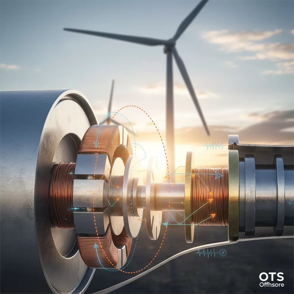
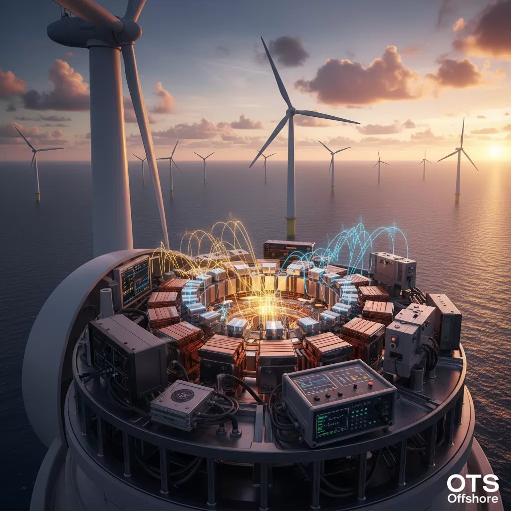
At the heart of the Analysis Principle Induction of induction generators lies the principle of electromagnetic induction, first described by Michael Faraday. This principle states that a voltage (and hence a current, if a circuit is closed) is induced in a conductor when it is exposed to a changing magnetic field. In an induction generator, this phenomenon is ingeniously harnessed. The stator of the induction generator contains a set of windings, typically arranged in three phases, which are supplied with AC power from the grid. When energized, these stator windings create a rotating magnetic field (RMF) that spins at a synchronous speed, determined by the grid frequency and the number of poles in the generator. This RMF is the crucial element in the Analysis Principle Induction.
The rotor of a squirrel-cage induction generator consists of conductive bars short-circuited at both ends by end rings, resembling a squirrel cage. As the wind turbine blades rotate the rotor, it moves through the RMF generated by the stator. Crucially, for the generator to produce power, the rotor must be driven at a speed slightly faster than the synchronous speed of the RMF. This difference in speed is known as “slip.” When the rotor rotates faster than the RMF, the relative speed between the magnetic field and the rotor conductors induces voltages and currents in the rotor bars. These induced rotor currents, in turn, create their own magnetic field. The interaction between the stator’s RMF and the rotor’s magnetic field generates a torque that opposes the rotor’s motion. This opposing torque, when overcome by the mechanical torque from the wind turbine blades, results in the rotor delivering mechanical power to the generator, which is then converted into electrical power. The Analysis Principle Induction emphasizes this slip-dependent torque generation.
The Role of Stator and Rotor in Induction Generation
The stator is the stationary part of the induction generator and houses the windings that create the fundamental rotating magnetic field. These stator windings are typically connected to the power grid. The configuration of these windings, along with the number of poles, dictates the synchronous speed of the magnetic field. For instance, a two-pole generator connected to a 60 Hz grid will have a synchronous speed of 3600 RPM, while a four-pole generator at the same frequency will run at 1800 RPM. Understanding the stator’s role is key to grasping the Analysis Principle Induction.
The rotor, as mentioned, is the rotating component. In squirrel-cage induction generators, its simplicity is a major advantage. The conductive bars are typically made of aluminum or copper, and the end rings provide a low-resistance path for the induced currents. Unlike wound-rotor induction machines, squirrel-cage rotors do not have external connections, making them highly reliable and maintenance-free. The relative speed between the RMF and the rotor conductors is what drives the induction process. As the rotor speed exceeds the synchronous speed, slip becomes negative, and the machine transitions from operating as a motor to operating as a generator. This transition is a critical aspect of the Analysis Principle Induction.

Types of Induction Generators in Wind Turbines
While the squirrel-cage induction generator (SCIG) is the most prevalent in wind turbines due to its simplicity and ruggedness, other types of induction generators are also employed, particularly in specific applications or for achieving certain performance characteristics. A deep Analysis Principle Induction of these variants reveals their distinct advantages and disadvantages.
– Doubly-fed induction generators (DFIGs): These are widely used in modern, variable-speed wind turbines. DFIGs offer advantages in terms of variable speed operation, allowing the turbine rotor to operate at speeds other than the synchronous speed, which can significantly improve energy capture efficiency. In a DFIG, both the stator and the rotor are connected to electrical circuits. The stator is directly connected to the grid, while the rotor windings are connected to the grid through a power converter system (often a back-to-back converter). This converter allows for controlled injection or absorption of power to and from the rotor, enabling speed control. The Analysis Principle Induction of DFIGs involves managing power flow through both stator and rotor circuits.
– Series-compensated induction generators: In some older or smaller turbine designs, series capacitors might be used to compensate for the generator’s inductive reactance, improving power factor and voltage regulation. This method offers a simpler approach to grid connection compared to DFIGs but provides less control over speed. The Analysis Principle Induction here focuses on the interaction of capacitive and inductive elements.
– Self-excited induction generators (SEIGs): These generators can operate independently of the grid, forming their own voltage and frequency through connection to a bank of capacitors. They are suitable for isolated applications or microgrids. Their operation relies on the build-up of residual magnetism and the presence of sufficient capacitance to sustain excitation. The Analysis Principle Induction of SEIGs is distinct due to their standalone nature.
Advantages and Disadvantages of Induction Generators
The widespread adoption of induction generators in wind turbines stems from a compelling set of advantages, which are further illuminated by a detailed Analysis Principle Induction.
Advantages:
– Robustness and reliability: Their simple construction, particularly for SCIGs, leads to high reliability and low maintenance requirements. This is crucial for offshore wind farms where maintenance is costly and challenging.
– Cost-effectiveness: SCIGs are generally less expensive to manufacture compared to synchronous generators or DFIGs.
– Direct grid connection: Simple induction generators can be directly connected to the grid without complex power electronics, simplifying installation and reducing initial costs.
– Simplicity of operation: Their asynchronous nature makes them relatively easy to operate and control, especially in fixed-speed applications.
Disadvantages:
– Reactive power consumption: Standard induction generators inherently consume reactive power from the grid to establish their magnetic field. This can negatively impact the power factor of the grid and requires compensation.
– Fixed-speed operation (for SCIGs): Standard SCIGs operate at a relatively fixed speed determined by the grid frequency and number of poles. This limits their ability to optimize energy capture under varying wind conditions.
– Difficulty in voltage and frequency control: Without sophisticated control systems, their output voltage and frequency are largely dictated by the grid.
The Operational Mechanism: Torque and Slip in Detail
A deeper dive into the Analysis Principle Induction reveals the intricate relationship between torque and slip. Torque is the rotational force produced by the generator, which is essential for converting mechanical energy into electrical energy. Slip, as defined earlier, is the difference between the synchronous speed of the RMF and the actual rotor speed, usually expressed as a percentage or a fractional value.
When the rotor speed is equal to the synchronous speed (i.e., slip is zero), no voltage is induced in the rotor, and therefore no torque is produced. This is the synchronous speed. For the generator to produce positive torque, the rotor must be driven at a speed faster than the synchronous speed. In generator operation, the slip (s) is negative. The formula for slip is: s = (Ns – Nr) / Ns, where Ns is the synchronous speed and Nr is the rotor speed. When Nr > Ns, s becomes negative.
The torque produced by an induction generator is directly proportional to the slip and the square of the stator voltage, and inversely proportional to the rotor resistance. The torque-speed characteristic of an induction generator shows that as the rotor speed increases beyond synchronous speed, the torque generally decreases. However, the critical aspect for generation is that this torque acts in the opposite direction of rotation, meaning it’s a braking torque. When the mechanical power input from the wind turbine exceeds the mechanical power loss (due to friction, windage, and core losses), the generator delivers net electrical power to the grid. Understanding this torque-slip relationship is fundamental to a precise Analysis Principle Induction.
Impact of Slip on Power Generation and Efficiency
The magnitude of slip plays a critical role in determining the power output and efficiency of an induction generator. In SCIGs, a small negative slip (typically 1-3%) is sufficient for them to operate as generators. A larger negative slip implies the rotor is spinning much faster than the synchronous speed, which can lead to increased rotor current and potential overheating. The Analysis Principle Induction highlights that while slip is necessary for torque, excessive slip can be detrimental.
The efficiency of an induction generator is influenced by various losses, including stator copper losses, rotor copper losses, core losses (hysteresis and eddy currents), and mechanical losses. These losses are present whether the machine is operating as a motor or a generator. The Analysis Principle Induction must account for these losses when assessing overall performance. The reactive power consumed by the generator also impacts the overall system efficiency and power factor.

Mathematical Modeling and Performance Analysis
The Analysis Principle Induction of induction generators is often supported by mathematical models that describe their electrical and mechanical behavior. The most common approach is using the equivalent circuit model, which represents the generator’s behavior using electrical components like resistances and reactances. This model allows for the calculation of various performance parameters such as torque, power output, efficiency, and power factor under different operating conditions.
The per-phase equivalent circuit of an induction generator is similar to that of an induction motor, with the key difference being the interpretation of slip. The rotor resistance term is adjusted based on the negative slip to reflect power generation. From this equivalent circuit, engineers can derive equations for:
– Torque: T = (3 * V_s^2 * R_r’) / (omega_s * ((R_r’/s)^2 + (X_s + X_r’)^2)) where V_s is stator voltage, R_r’ is the equivalent rotor resistance referred to the stator, omega_s is synchronous angular speed, s is slip, X_s is stator leakage reactance, and X_r’ is rotor leakage reactance referred to the stator.
– Power output: P_out = T * omega_r, where omega_r is the actual rotor angular speed.
– Efficiency: eta = P_out / P_in, where P_in is the total input power.
These mathematical tools are indispensable for a thorough Analysis Principle Induction, enabling designers to optimize generator parameters for specific wind turbine applications.
Controlling Induction Generators for Grid Integration
While simple induction generators can be directly connected to the grid, controlling them for optimal performance and stable grid integration, especially in variable-speed wind turbines, requires advanced techniques. The Analysis Principle Induction extends to the control strategies employed.
– Fixed-speed operation: For SCIGs directly connected to the grid, speed is dictated by the grid. Reactive power compensation, usually through capacitor banks, is employed to improve the power factor.
– Variable-speed operation (DFIGs): DFIGs utilize power converters to control the rotor circuit. This allows the turbine to operate over a range of speeds, optimizing aerodynamic efficiency. The converter also enables control of active and reactive power output, improving grid stability and power quality. Advanced control algorithms, such as vector control, are used to precisely manage the DFIG’s performance. The Analysis Principle Induction here considers the dynamic interplay between the generator and the converter.
The integration of induction generators into the power grid is a complex process that involves ensuring seamless power transfer, maintaining voltage and frequency stability, and managing grid disturbances. A comprehensive Analysis Principle Induction considers these aspects to ensure reliable and efficient renewable energy supply.


