Designing Multi-Stage Gearboxes for Wind Turbines is crucial for optimizing energy capture across varying wind conditions, particularly for low and high wind speeds. This article delves into the intricate engineering principles and considerations involved in creating these complex mechanical systems, ensuring efficient and reliable power generation.
The Critical Role of Designing Multi-Stage Gearboxes for Wind Turbines
Designing Multi-Stage Gearboxes for wind turbines represents a cornerstone of modern renewable energy technology. These intricate mechanical assemblies are responsible for translating the slow, high-torque rotation of the rotor into the high-speed, low-torque rotation required by the electrical generator. The efficiency and reliability of this power conversion are paramount, especially when considering the wide spectrum of wind conditions turbines are expected to operate within. From the gentle zephyrs of low wind speed sites to the powerful gusts of high wind speed environments, the gearbox must perform optimally, minimizing energy losses and maximizing power output while enduring significant mechanical stresses.
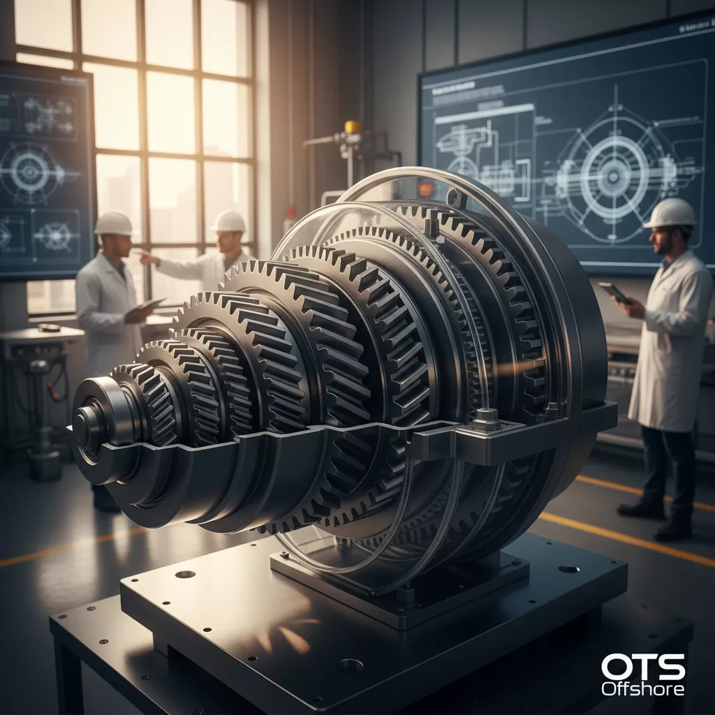
The complexity arises from the need to achieve substantial speed increases within a compact and robust package. A single-stage gearbox would be impractically large and inefficient for the typical operational requirements of a wind turbine. Therefore, multi-stage designs, employing several sets of gears, become essential. The process of Designing Multi-Stage Gearboxes is a multidisciplinary endeavor, involving sophisticated mechanical design, materials science, lubrication engineering, thermal management, and advanced manufacturing techniques. Each stage of the gearbox contributes to the overall gear ratio, and the careful selection of gear types, tooth profiles, bearing configurations, and housing designs dictates the gearbox’s performance characteristics.
Furthermore, the operational environment of a wind turbine presents unique challenges. Gearboxes are exposed to extreme temperature fluctuations, humidity, dust, and vibrations. Designing Multi-Stage Gearboxes must account for these factors to ensure longevity and prevent premature failure. This includes selecting appropriate sealing mechanisms, robust materials that can withstand fatigue and wear, and sophisticated lubrication systems to reduce friction and dissipate heat effectively. The economic viability of wind energy heavily relies on the performance and lifespan of its components, making the meticulous process of Designing Multi-Stage Gearboxes a critical area of research and development in the wind energy sector. Understanding the nuances of Designing Multi-Stage Gearboxes is key to unlocking the full potential of wind power generation.
Understanding the Wind Speed Spectrum and Gearbox Demands
Wind speed is the primary driver of a wind turbine’s power output. It’s not a static value but fluctuates constantly. For the purpose of gearbox design, wind speeds are often categorized into distinct ranges, each posing unique challenges.
– Low wind speeds: These are the speeds at which a turbine begins to generate power (cut-in speed) and the range where energy capture is minimal. During these periods, the rotor spins slowly, producing very low torque. The gearbox must efficiently amplify this low torque to a speed sufficient for the generator to produce electricity. This requires a high overall gear ratio. The stresses on the gears and bearings are generally lower, but the need for low-friction operation and efficient power transfer is critical to making operation viable. Capturing every watt of energy in low winds is crucial for the overall economic performance of a wind farm.
– Moderate wind speeds: This is the optimal operating range where the turbine generates its rated power. The gearbox operates under significant loads but within its designed parameters. Efficient power transmission and thermal management are key concerns here to prevent overheating and maintain peak performance.
– High wind speeds: Beyond the rated wind speed, the turbine’s pitch control system adjusts the blade angle to maintain constant power output, preventing damage. During these periods, the gearbox experiences high torque and significant inertial loads, especially during gusts. The structural integrity and fatigue resistance of the gearbox components are paramount. Designing Multi-Stage Gearboxes for these conditions requires robust materials, conservative stress calculations, and effective damping mechanisms. The gearbox must be able to withstand these demanding conditions without compromising its operational lifespan.
– Very high wind speeds: Above a certain threshold (cut-out speed), the turbine shuts down to protect itself from damage. The gearbox must be able to safely disengage or withstand the forces during shutdown and restart.
The challenge in Designing Multi-Stage Gearboxes is to create a single system that can efficiently and reliably handle these vastly different operational demands. This often involves compromises and sophisticated engineering solutions.
Key Principles in Designing Multi-Stage Gearboxes
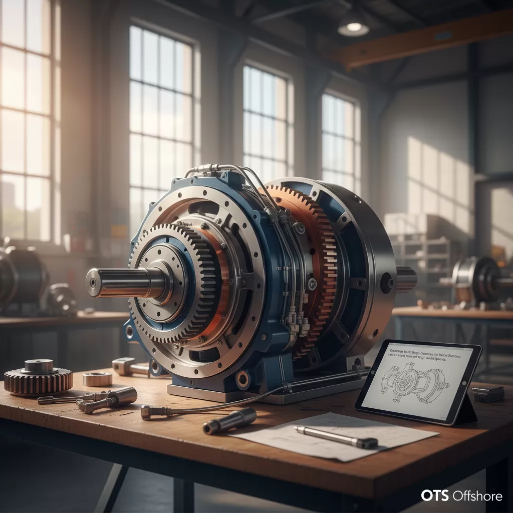
The core of Designing Multi-Stage Gearboxes lies in achieving a specific gear ratio through multiple stages of reduction. Each stage typically involves a pair of meshing gears. The overall gear ratio is the product of the ratios of each individual stage.
– Gear Ratio Calculation: The desired overall gear ratio is determined by the optimal rotational speed of the rotor (typically 10-20 RPM for large turbines) and the required input speed for the generator (typically 1000-1800 RPM). For example, to achieve a ratio of 100:1, one might employ a double-stage reduction where each stage provides a ratio of approximately 10:1.
– Gear Types: The selection of gear types is crucial.
– Spur gears: Simple, cost-effective, but can be noisy and less efficient for high loads and speeds.
– Helical gears: Offer smoother engagement, higher load-carrying capacity, and quieter operation than spur gears due to their angled teeth. They are widely used in wind turbine gearboxes.
– Bevel gears: Used for changing the direction of rotation, often in combination with helical gears.
– Planetary (epicyclic) gears: Offer a compact design with high torque density and can be very efficient. They are increasingly being considered and used in advanced turbine designs, especially for direct-drive or hybrid systems.
– Tooth Profile and Contact Ratio: The shape of the gear teeth (e.g., involute profile) and the number of teeth in contact at any given time (contact ratio) significantly impact load-carrying capacity, stress distribution, and noise generation. A higher contact ratio generally leads to smoother operation and reduced stress.
– Bearing Selection: Bearings are critical for supporting the rotating shafts and minimizing friction. Types include:
– Roller bearings (cylindrical, spherical, tapered): Offer high load-carrying capacity and are commonly used for main shaft and intermediate shaft support.
– Ball bearings: Used for lower load applications or thrust loads.
Proper bearing selection ensures longevity and minimizes power losses.
– Lubrication System Design: Effective lubrication is vital for reducing friction, dissipating heat, and preventing wear. This involves selecting the right lubricant viscosity, designing a robust oil circulation system (including pumps, filters, and coolers), and ensuring proper oil distribution to all meshing gears and bearings. For Designing Multi-Stage Gearboxes, ensuring adequate lubrication across all stages, especially under varying load conditions, is a significant engineering challenge.
– Thermal Management: Gearbox operation generates heat due to friction. Inadequate heat dissipation can lead to lubricant breakdown, material fatigue, and premature failure. Designing Multi-Stage Gearboxes must incorporate cooling strategies, such as oil coolers, or optimize airflow around the gearbox housing.
– Material Selection: Gears and shafts are typically made from high-strength steel alloys. The choice of material depends on the expected stresses, fatigue life requirements, and manufacturing capabilities. Case hardening and surface treatments are often applied to improve wear resistance.
Multi-Stage Gearbox Architectures for Different Wind Conditions
Designing Multi-Stage Gearboxes necessitates tailoring the architecture to the specific operational environment. For wind turbines, the prevailing wind speed regime often dictates the optimal gearbox configuration.
– Three-Stage Helical Gearboxes: This is a very common architecture for medium to large-sized wind turbines. It typically consists of a single-stage low-speed input gear (connected to the rotor shaft) and two stages of high-speed reduction using helical gears. This configuration provides a substantial gear ratio and is well-suited for moderate to high wind speed sites. The first stage often has a larger gear ratio to achieve a significant speed increase early in the power train.
– Two-Stage Gearboxes: While less common for very large turbines requiring high ratios, two-stage gearboxes can be suitable for turbines operating in consistently higher wind speed regions or for smaller turbines. They are generally simpler, lighter, and potentially more efficient due to fewer power transfer points, but they offer a lower overall gear ratio.
– Planetary Gearbox Integration: Planetary gear systems are known for their compact size and high torque density, making them attractive for Designing Multi-Stage Gearboxes.
– Hybrid designs: Often, a planetary stage is combined with helical stages. A common configuration might be a planetary stage followed by one or two helical stages. This can offer benefits in terms of weight reduction and improved torque distribution.
– Full planetary gearboxes: Some advanced turbine designs might employ multiple planetary stages to achieve very high gear ratios within a compact volume. This requires sophisticated bearing and lubrication design within the planetary carrier.
– Direct Drive Systems (No Gearbox): While not a gearbox solution, it’s worth noting that direct drive systems eliminate the gearbox entirely by using generators that operate at rotor speed. These systems have significantly fewer moving parts and potentially higher reliability but require larger, heavier, and more expensive generators, especially for low wind speed applications. The trade-off between gearbox complexity and generator size and cost is a key consideration in turbine design.
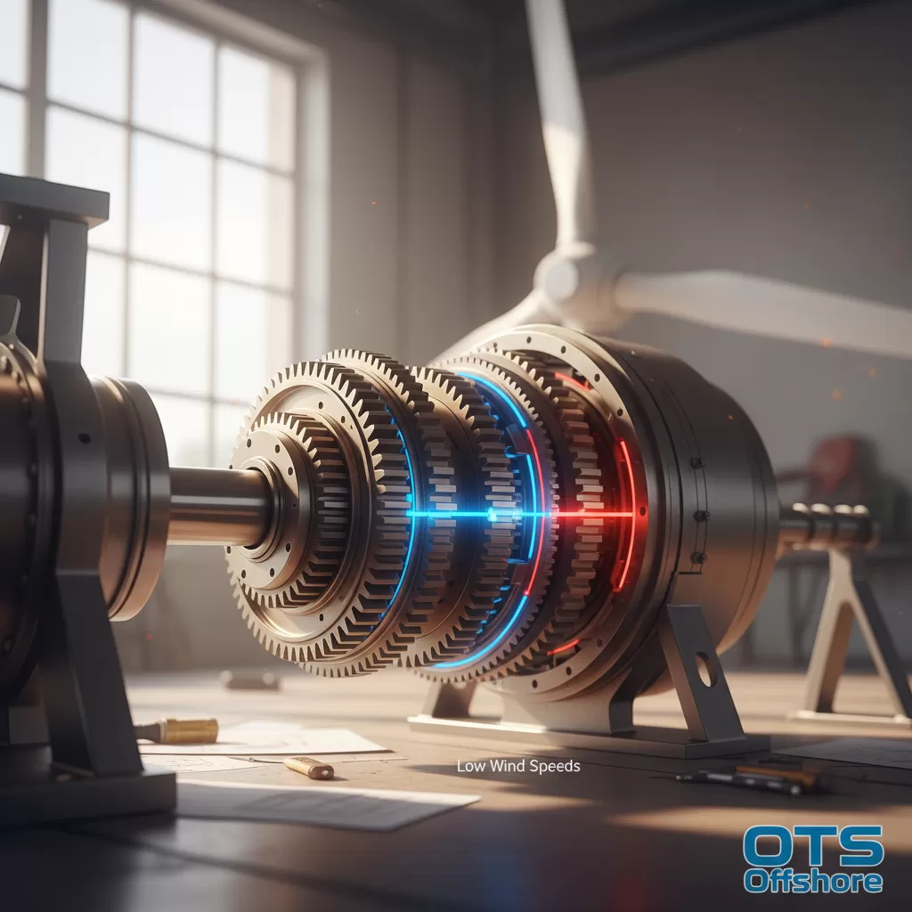
For low wind speed turbines, Designing Multi-Stage Gearboxes often prioritizes achieving a very high overall gear ratio to maximize the generator’s operational speed from slow rotor turns. This might lead to more stages or a higher ratio in the initial stages. For high wind speed turbines, the emphasis shifts towards robustness, load-carrying capacity, and thermal management to withstand the significant forces encountered. Redundant bearing arrangements and stronger gear teeth profiles become more critical.
Advanced Considerations in Gearbox Design
Beyond the fundamental principles, several advanced considerations are crucial for modern Designing Multi-Stage Gearboxes.
– Load Spectrum Analysis: A thorough understanding of the load spectrum the gearbox will experience throughout its operational life is critical. This includes not only steady-state loads but also transient loads from wind gusts, grid events, and start-stop cycles. Finite Element Analysis (FEA) is extensively used to simulate stress and deformation under these various load conditions.
– Fatigue Life Prediction: Gear teeth and bearings are subject to cyclic loading, which can lead to fatigue failure. Sophisticated models are used to predict the fatigue life of components based on material properties, stress levels, and the expected number of cycles. Designing Multi-Stage Gearboxes aims to exceed the turbine’s designed lifespan (typically 20-25 years).
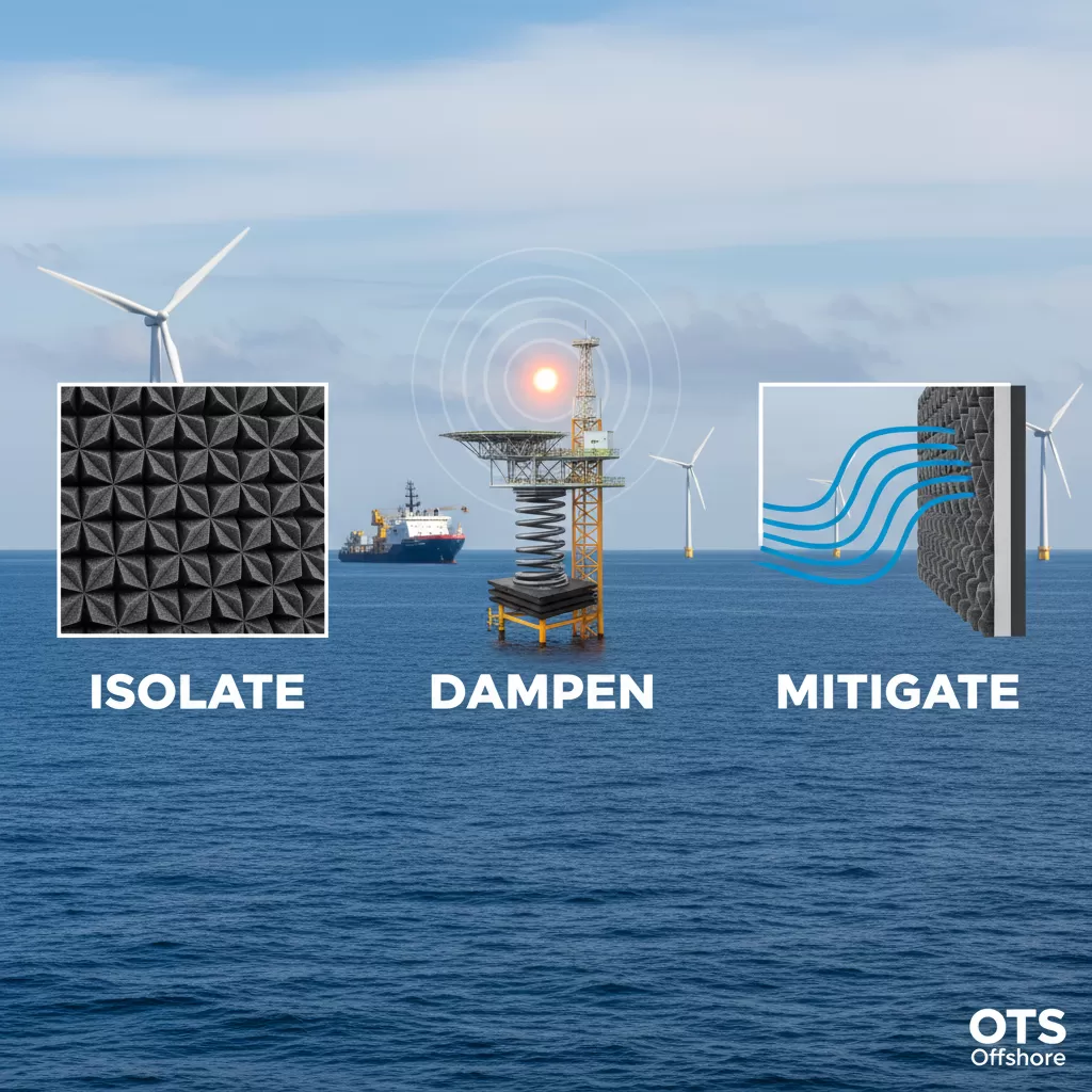
– Noise and Vibration Mitigation: Gearboxes can be a significant source of noise and vibration in wind turbines. Advanced tooth meshing design, precise manufacturing tolerances, and damping elements are employed to minimize these issues, which can affect public acceptance and component longevity.
– Condition Monitoring Systems (CMS): Integrating sensors for monitoring parameters like vibration, temperature, and oil quality is becoming standard. These systems allow for early detection of potential faults, enabling proactive maintenance and preventing catastrophic failures. This data also feeds back into the design process for future iterations of Designing Multi-Stage Gearboxes.
– Reliability and Maintainability: Designing Multi-Stage Gearboxes must consider ease of maintenance and potential repair. Modular designs, accessible lubrication points, and standardized components can simplify servicing. Redundancy in critical systems, such as lubrication pumps, can also enhance overall reliability.
– Efficiency Optimization: Minimizing mechanical losses within the gearbox is a continuous goal. This involves reducing friction in gear meshes and bearings through optimized tooth profiles, advanced coatings, and low-viscosity lubricants where appropriate. Even small percentage gains in efficiency translate to significant increases in energy production over the turbine’s lifetime.
– Scalability: The design principles for Designing Multi-Stage Gearboxes must be scalable to accommodate a wide range of turbine sizes, from small distributed generation units to gigawatt-scale offshore turbines. This requires a robust understanding of how scaling affects torque, speed, and power density.
The continuous evolution of materials, manufacturing techniques, and computational tools allows for increasingly sophisticated and optimized Designing Multi-Stage Gearboxes, pushing the boundaries of wind energy efficiency and reliability.

