Inspection Structural Flaws: plays a critical role in ensuring the integrity and longevity of offshore platforms, pipelines, and other vital energy infrastructure. This article delves into the multifaceted approach to identifying and mitigating common structural defects such as blisters, laminations, weld misalignment, and distortion, highlighting their implications for operational safety and asset management within the oil and gas sector.
Inspection Structural Flaws: Essential Strategies for Offshore Assets
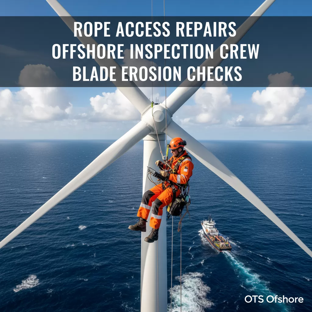
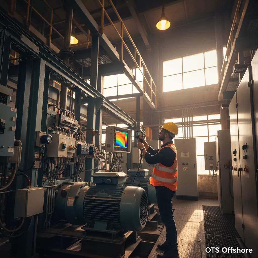
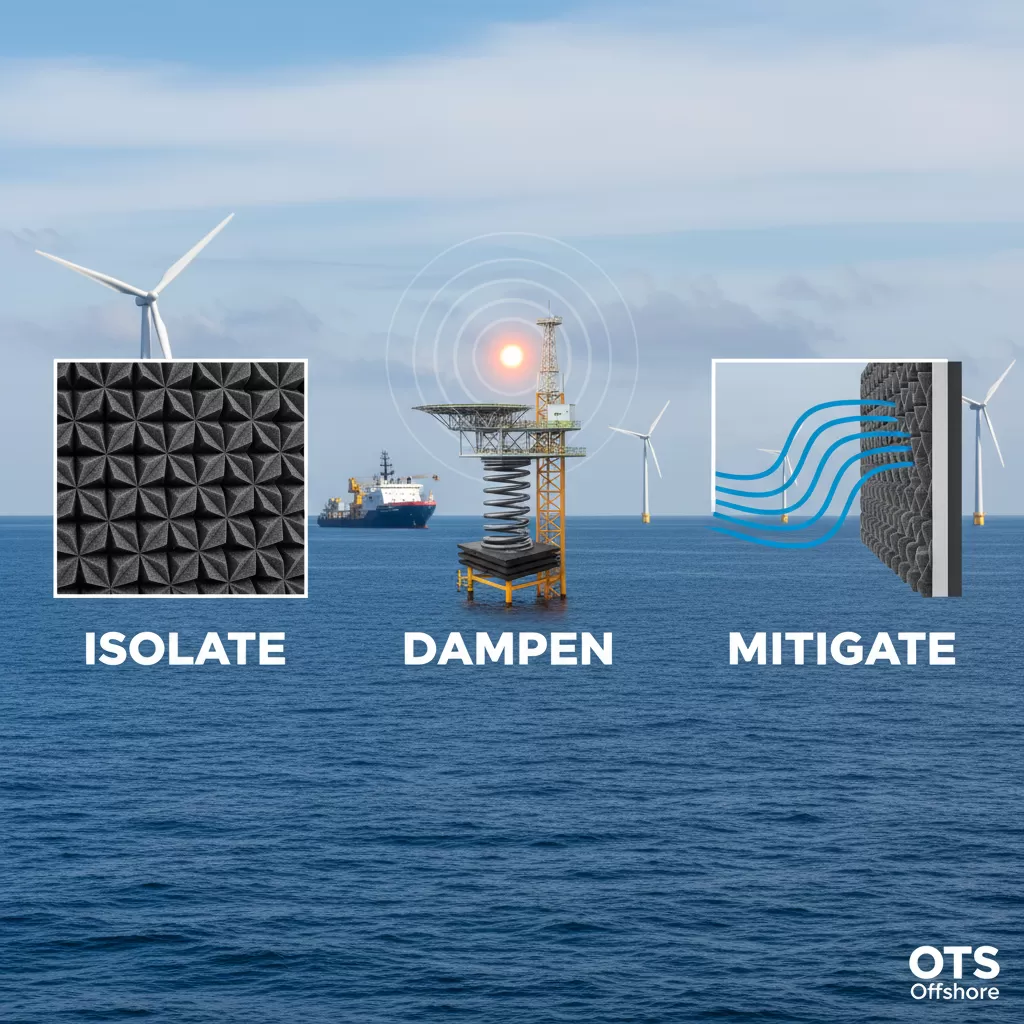
The proactive and rigorous Inspection of Structural Flaws is paramount in safeguarding the operational integrity of the global oil and gas industry. From the towering offshore platforms that extract vital resources to the intricate network of subsea pipelines that transport them, the structural soundness of these assets is non-negotiable. Failure to identify and address developing defects can lead to catastrophic consequences, including environmental damage, significant financial losses, and, most importantly, jeopardized human safety. This comprehensive examination focuses on four prevalent types of structural imperfections: blisters, laminations, weld misalignment, and weld distortion. Understanding their origins, detection methods, and mitigation strategies is a cornerstone of effective asset integrity management and a continuous priority for engineering and inspection teams worldwide. The evolving landscape of inspection technologies and methodologies underscores the industry’s commitment to staying ahead of potential vulnerabilities.
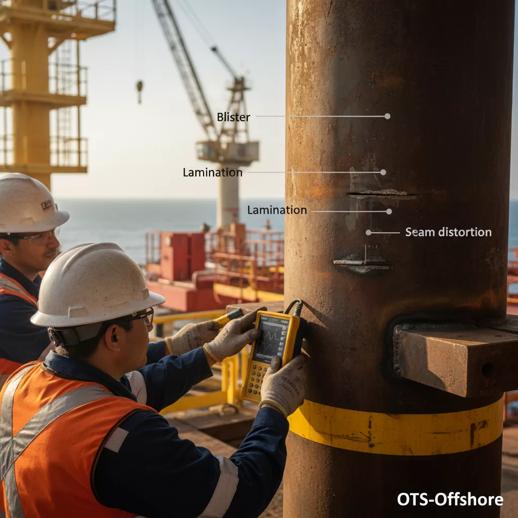
Understanding Blisters and Laminations in Steel Structures
Blisters and laminations are internal defects that can compromise the structural integrity of steel components, particularly in welded sections and rolled plates used in the energy sector. These flaws often originate during the manufacturing process of the steel itself or during subsequent fabrication stages.
The Genesis of Blisters
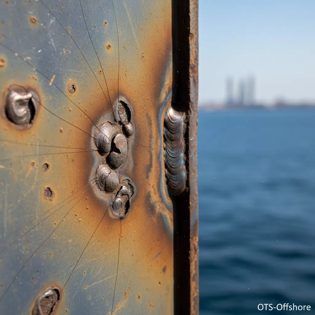
Blisters in steel typically manifest as small, raised bubbles or pockets on the surface of the material, or they can be subsurface. Their formation is commonly attributed to the presence of trapped gases or volatile elements within the molten steel during casting or solidification. As the steel cools and solidifies, these trapped gases create voids or pressure points that lead to the formation of these blisters. In the context of welding, blisters can also arise from the entrapment of hydrogen in the weld metal, particularly in the presence of moisture. This hydrogen can diffuse into the steel and, upon cooling, react with inclusions or form voids, leading to blistering. The presence of blisters can reduce the effective cross-sectional area of a component, potentially weakening it under stress.
The Nature of Laminations
Laminations, on the other hand, are planar discontinuities that run parallel to the surface of the steel. They represent a separation or lack of fusion between layers of the steel during its rolling process. Imagine the steel being rolled out from a thick slab; if there are impurities or inadequate working of the material, these layers may not bond completely, leaving internal gaps. These gaps are laminations. They are often a result of rolled-in scale, slag inclusions, or segregation of impurities in the ingot. Laminations can significantly impair the mechanical properties of the steel, particularly its toughness and resistance to fracture, especially in the through-thickness direction. They can act as crack initiation sites and propagate under cyclic loading or stress concentrations.
Inspection Methods for Blisters and Laminations
Detecting blisters and laminations requires a systematic approach utilizing various non-destructive testing (NDT) techniques.
– Visual Inspection: For surface-breaking blisters, a thorough visual examination by trained inspectors can often identify their presence. However, subsurface blisters may remain undetected.
– Ultrasonic Testing (UT): UT is a primary method for detecting both blisters and laminations. By sending sound waves into the material and analyzing the reflected echoes, UT can identify internal discontinuities. Laminations, being planar, often cause significant reflections as the sound waves encounter the interface between the layers. For blisters, the spherical or irregular shape of the void will also cause characteristic reflections. Phased array UT (PAUT) offers advanced capabilities for characterizing the size and depth of these flaws.
– Radiographic Testing (RT): While less common for routine detection of these specific flaws compared to UT, RT can reveal voids and internal discontinuities like blisters. However, its effectiveness for detecting planar laminations can be limited depending on their orientation relative to the X-ray beam.
– Eddy Current Testing (ECT): For surface and near-surface defects, ECT can be a useful tool. It works by inducing eddy currents in the conductive material and detecting disturbances caused by surface flaws such as blisters.
Implications and Mitigation
The presence of blisters and laminations can lead to premature failure of critical components, impacting the structural integrity of offshore facilities. Mitigation strategies often involve:
– Material selection: Employing higher quality steels with cleaner internal structures and proper deoxidation practices during manufacturing can minimize the risk of laminations and blisters.
– Fabrication controls: Strict control over welding procedures, including proper preheating and post-weld heat treatment (PWHT) to control hydrogen diffusion, can prevent blister formation.
– Repair or replacement: If significant blisters or laminations are detected and deemed to compromise the structural integrity, the affected component may require repair (e.g., grinding out and re-welding, if applicable and permissible) or complete replacement.
Addressing Weld Misalignment and Distortion: A Critical Challenge
Welding is a fundamental process in the fabrication and repair of oil and gas infrastructure. However, the heat input and material transformations associated with welding can inevitably lead to geometric imperfections such as misalignment and distortion, which can have profound implications for structural integrity.
The Root Causes of Weld Misalignment
Weld misalignment, also known as fit-up mismatch or offset, occurs when the edges of the components being joined are not perfectly aligned in their intended positions. Several factors contribute to this:
– Inaccurate Cutting and Preparation: Imperfectly cut edges or incorrect bevel preparation can lead to misalignment even before welding commences.
– Fixturing and Clamping Issues: Inadequate or poorly designed fixturing and clamping systems may not hold the components in their precise locations during the welding process, allowing them to shift.
– Material Properties and Tolerances: Variations in material thickness, inherent curvature in plates, or exceeding manufacturing tolerances can create challenges in achieving perfect alignment.
– Welding Sequence: The order in which welds are made can influence the final position of components. Improper sequencing can induce stresses that lead to shifts.
– Operator Skill: While less of a primary cause, an operator’s ability to maintain alignment during tack welding and the initial stages of the main weld can play a role.
Understanding Weld Distortion
Weld distortion refers to the undesirable deformation of welded structures caused by the uneven heating and cooling cycles inherent in welding. The localized heat input causes expansion and contraction of the metal. As the molten weld metal solidifies and cools, it shrinks. This shrinkage, when occurring in an unrestrained or partially restrained structure, generates internal stresses that manifest as plastic deformation, leading to bending, buckling, warping, or twisting of the components.
– Thermal Gradients: The rapid temperature changes create significant thermal gradients across the weld area and the surrounding material.
– Differential Cooling: Different parts of the weld and base material cool at different rates, leading to differential shrinkage.
– Residual Stresses: These stresses, if not managed, can contribute to distortion and can also reduce the component’s resistance to fatigue and fracture.
Inspection and Assessment of Misalignment and Distortion
Detecting and quantifying weld misalignment and distortion is crucial for determining their impact on structural performance.
– Dimensional Checks: The most straightforward method involves using measuring tools like tape measures, rulers, calipers, and gauges to verify dimensions and offsets against design specifications.
– Laser Scanning and Photogrammetry: For complex geometries or large structures, advanced techniques like 3D laser scanning and photogrammetry provide highly accurate digital models of the as-welded condition, allowing for precise comparison with the intended design.
– NDT Techniques for Indirect Assessment: While NDT methods like UT and RT are primarily for flaw detection within the weld itself, they can indirectly help assess the consequences of distortion if it leads to unusual weld profiles or stresses.
Mitigation Strategies for Weld Misalignment and Distortion
Preventing and managing weld misalignment and distortion requires a multi-pronged approach that begins during the design and fabrication planning phases.
– Design Considerations: Designing with weldability and distortion in mind is key. This might involve specifying appropriate joint types, considering weld sequences, and incorporating features that can accommodate some degree of deformation.
– Precise Fit-Up and Fixturing: Investing in accurate cutting technologies and robust fixturing and clamping systems is essential to maintain alignment during welding. This includes using jigs, braces, and temporary supports.
– Controlled Welding Procedures: Employing controlled welding parameters such as current, voltage, travel speed, and heat input is vital. Low heat input welding processes can help minimize thermal distortion.
– Strategic Welding Sequence: Developing and adhering to a carefully planned welding sequence can significantly reduce distortion. This often involves welding symmetrically, balancing heat input on opposite sides of the structure, and using intermittent welds rather than long continuous ones where possible.
– Backstep Welding and Balanced Welding: Techniques like backstep welding (where short weld segments are deposited in a backward direction relative to the overall progression) and balanced welding (where welding is performed on opposite sides of a joint simultaneously or in rapid alternation) can help counteract shrinkage forces.
– Stress Relief: For critical components, post-weld heat treatment (PWHT) can be employed to reduce residual stresses and potentially alleviate some distortion. However, PWHT itself can induce further distortion if not carefully controlled.
– Line Warming (for pipelines): In pipeline construction, carefully controlled line warming processes can help manage stresses and prevent distortion during welding.
– Repair and Correction: In cases where misalignment or distortion exceeds acceptable limits, repairs may be necessary. This could involve cutting out the faulty weld and re-welding with improved fit-up, or in some instances, employing mechanical means to straighten components, though this can be challenging and may induce further stresses.
The diligent inspection and management of structural flaws, including blisters, laminations, weld misalignment, and distortion, are not merely compliance exercises. They are fundamental pillars of operational excellence, safety assurance, and economic sustainability within the demanding environment of the oil and gas industry. The continuous refinement of inspection technologies and the unwavering commitment to robust engineering practices ensure the reliable performance of critical energy infrastructure for years to come.
