

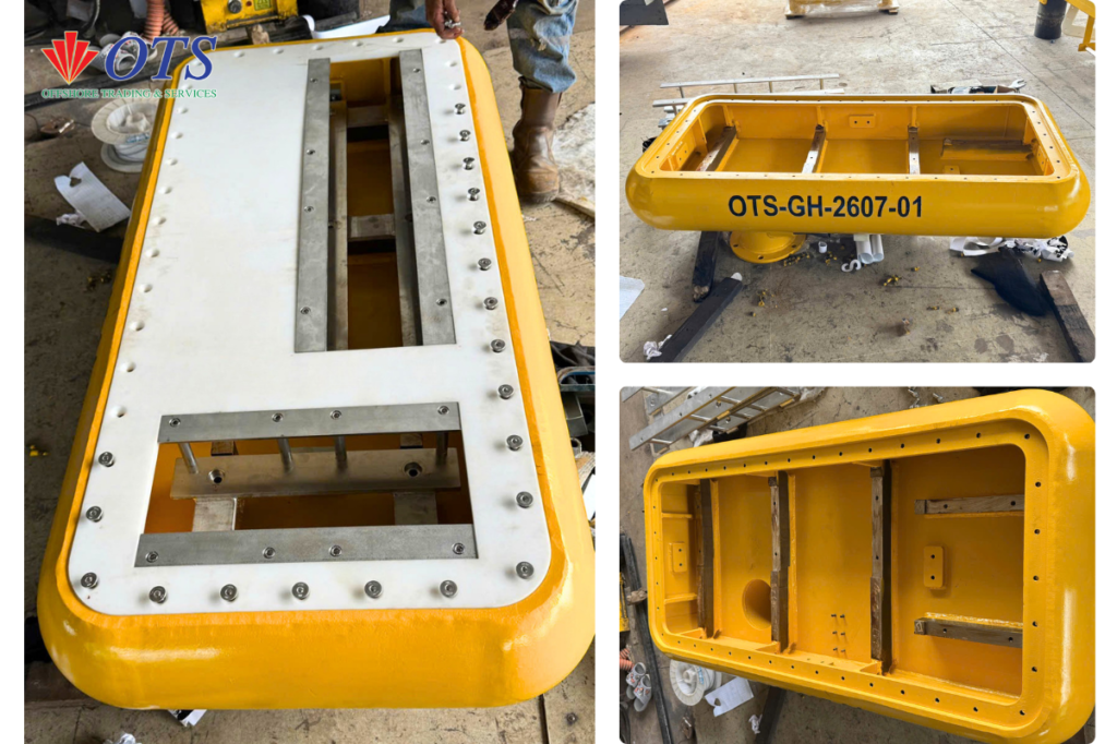
A survey vessel’s acoustic sensors are only as good as their mounting. Even a world-class MBES or SBP transducer will underperform if it isn’t held perfectly still, perfectly aligned, and shielded from drag and fouling below the hull. That’s the exact job of the OTS Gondola Housing — the lower assembly of the OTS Gondola System, built specifically to interface, align and protect the vessel’s acoustic sensors.
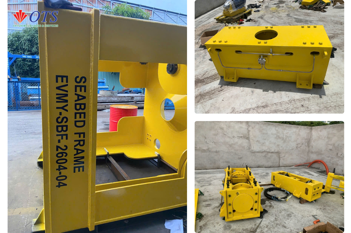
The Gondola Housing is engineered around two tightly integrated components: the Lower Mounting Base and the Composite Housing (Transducer Slot).
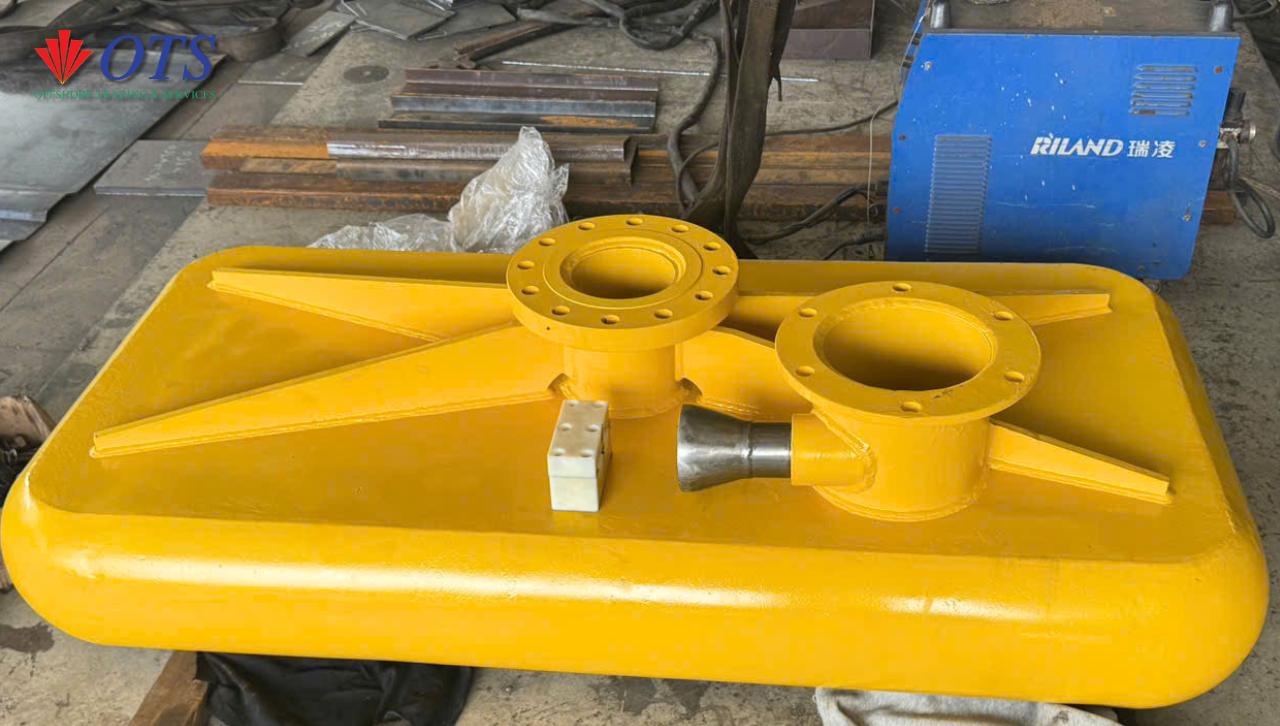
🔹 Lower Mounting Base
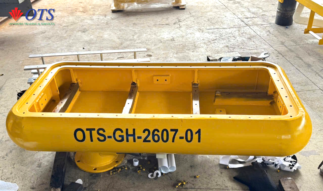
The Lower Mounting Base is the structural connection point between the Gondola Housing and the deployment frame above it. Key features include:
- Dual flanged connection holes, engineered for a precise, repeatable connection to the upper mounting frame
- Precision-machined mounting interface, holding tight dimensional tolerances so the housing seats correctly every time
- Direct load transfer path — the base carries hydrodynamic and structural loads from the housing up through the mounting frame into the vessel’s hull structure
Because survey accuracy depends on the sensor staying in exactly the same position relative to the hull, the Lower Mounting Base is where that positional accuracy is either preserved — or lost. OTS controls this interface to close tolerances during fabrication, so alignment doesn’t drift once the system is in service.
🔹 Composite Housing (Transducer Slot)
The Composite Housing is the hydrodynamic enclosure that sits below the mounting base, with a dedicated slot designed to hold, align and protect the acoustic transducer itself. Key features include:
- Transducer slot engineered to the sensor’s mounting geometry, keeping the transducer face correctly positioned and protected
- Composite construction, selected for its combination of structural strength, corrosion resistance and reduced weight compared to an all-steel enclosure
- Hydrodynamic profile, shaped to minimize drag and flow-induced turbulence that could otherwise introduce acoustic noise and degrade sensor performance
- Physical protection for the transducer against impact, debris and marine fouling during offshore operation
Why the Lower Mounting Base and Composite Housing Are Engineered Together
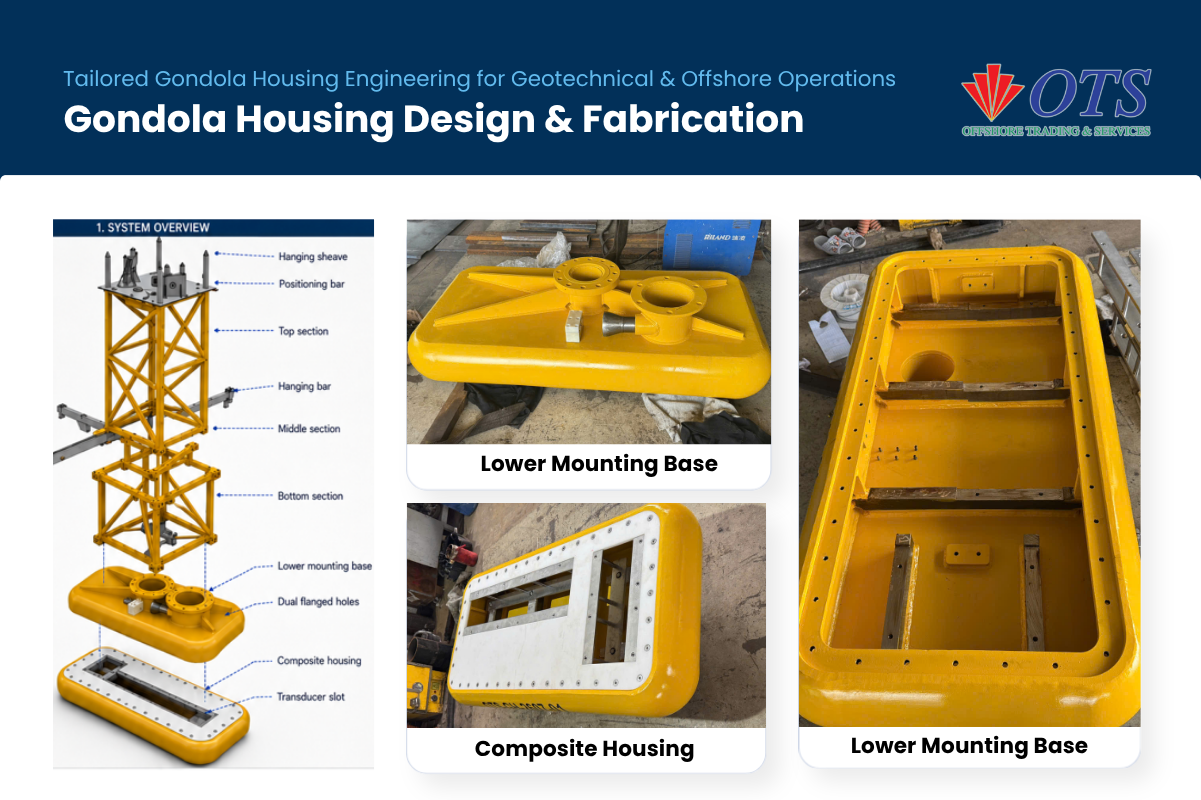
These two components can’t be designed in isolation — the mounting base sets the structural and positional reference, while the housing determines the hydrodynamic and sensor-protection performance. OTS engineers both as a single interconnected assembly, accounting for:
- Sensor alignment accuracy across the mounting base–to–transducer interface
- Hydrodynamic drag of the combined housing profile under vessel motion
- Structural load transfer from the housing, through the mounting base, into the deployment frame and hull
- Vessel-specific geometry — flange spacing, transducer type (MBES, SBP, USBL) and hull mounting points differ from vessel to vessel, so each housing is engineered rather than pulled from a catalogue
Why Housing Precision Directly Affects Acoustic Data Quality
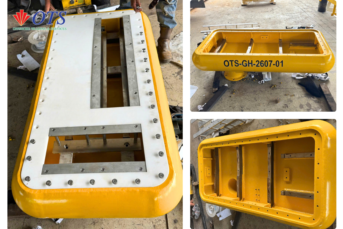
The housing isn’t just a protective shell — its shape and fit directly affect the data the transducer collects.
- Hydrodynamic profile and acoustic noise. A poorly shaped housing creates turbulent flow that raises the sensor’s noise floor and masks weak returns. An optimized profile keeps flow smooth at survey speed.
- Mounting-interface accuracy and alignment drift. Loose tolerances can shift the transducer’s boresight angle — even a fraction of a degree becomes positioning error at range, often invisible until post-processing.
- Fit tolerance and long-term reliability. An imprecise flanged connection risks vibration and fatigue over time, and makes the housing harder to reseat accurately at each maintenance cycle.
This is why OTS engineers the mounting base and composite housing as one assembly — the tolerances that protect data quality are set at the interface between them.
Fabrication & Quality

The Gondola Housing is fabricated under the same quality system as the rest of the OTS Gondola System — welding to EN ISO 3834-2, structural execution to EN 1090-2 EXC3, FEA-verified before fabrication, and NDT-inspected on completion, with marine coating applied for long-term corrosion resistance. Full process detail is covered in our main Gondola System article.
Built to Order for Your Vessel and Sensor Package
Because flange spacing, transducer dimensions and hull mounting points vary by vessel, OTS engineers each Lower Mounting Base and Composite Housing to your specific sensor package — whether MBES, SBP or USBL. Talk to our engineering team about your vessel’s mounting requirements and sensor specifications, and we’ll scope a housing assembly from design through to load-tested delivery.